




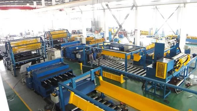


Digima W0194Z reinforcement production line
Fully automatic wire mesh welding machine


| No. | Description | Quantity |
|---|---|---|
| 1 | Longitudinal wire straightening system1 set | |
| 2 | Transverse wire straightening system | 1 set |
| 3 | Longitudinal wire feeding system | 1 set |
| 4 | Longitudinal wire storage system | 1 set |
| 5 | Longitude wire straightening system | 1 set |
| 6 | Wire mesh welding machine | 1 set |
| 7 | Mesh tensioning system | 1 set |
| 8 | Mesh cutting machine | 1 set |
| 9 | Mesh stacking system | 1 set |
| 10 | Rolled mesh system | 28M |
| 11 | Fully automatic longitudinal wire feeding system | 1 set |
| 12 | Automatic wire straightening and cutting machine | 1 set |
| 13 | Butt welding machine | 1 set |
| 14 | Pressure tower with cooling function | 1 set |
| 15 | Including cables from the welding equipment to the control cabinets. Cables from the factory transformer to the control cabinet. Control cabinets should be supplied by the purchaser. | |
Power supply requirements
For single-pass welding, the power supply capacity should be at least 1000 kVA.
Air pressure requirements
The air compressor capacity should be at least 6 m³/min, and the rated outlet pressure should be at least 0.8 MPa. An air tank with a capacity of at least 1 m³ and a pressure of 0.9 MPa must be placed next to the welding equipment. W0194Z Production line 960,000 PLN NET
The air compressor’s capacity should be no less than 4 m³/min, and its rated outlet pressure
The pressure should not be lower than 0.8 MPa. The gas cylinder should be positioned next to the welding equipment; its capacity should not be less than 1 m³, and the pressure should be 0.9 MPa.
Requirements for the water supply It is recommended to use a recirculating cooling system, with a tank capacity of not less than 10 m³,a pump head of approximately 15 m, and a flow rate greater than 250 l/min.
Workforce requirements: Total: 4 people, one to operate the controller, one to feed the wire, and the other two to periodically unload the sheets.
Site requirements: Machine dimensions: 65 m (L) × 8 m (W) × 3 m (H); additional space is required for the wire and the finished mesh.
| Diameter | Materials (g/m) | Speed (min⁻¹) | Output (kg/min) | Output (t/h) |
|---|---|---|---|---|
| Ø5 | 154 | 50 | 37 | 2.22 |
| Ø6 | 222 | 45 | 48 | 2.88 |
| Ø8 | 394 | 40 | 75 | 4.5 |
| Ø10 | 616 | 35 | 103 | 6.1 |
| Ø12 | 888 | 30 | 128 | 7.5 |
2. List of equipment .1 Wire unwinder
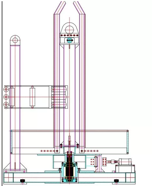
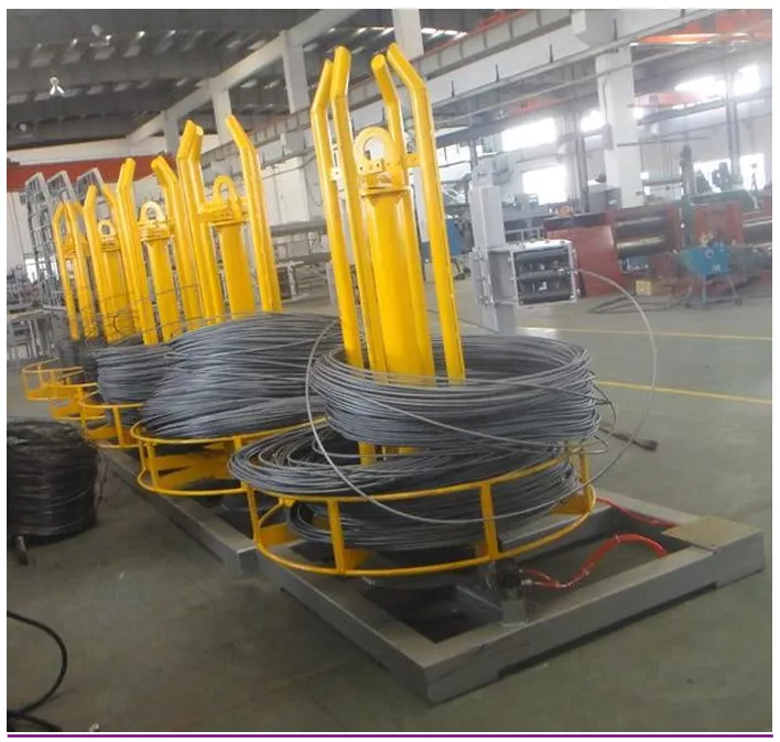
Wire decoilers (linear wires from a coil/load for each: 2000 kg)
Inner diameter (ID): 388–768 mm l
Outer diameter (OD): 1400 mm
Steel wire coils: 2000 kg
Weight of each decoiler: 750 kg Overall dimensions: 1.6 m × 1.6 m × 2.2 m (length × width × height).
2.2 Device for straightening and feeding straight wire
Straightening and feeding unit for continuous wire The continuous wire straightening unit is situated between the loading reel and the storage rack. It is used to straighten linear wire prior to welding and to straighten linear wire fed from the storage rack. The wire straightening and feeding unit consists of a guide unit, a vertical straightening unit, a horizontal straightening unit, a pneumatic unit, a clamping unit and a drive unit. The loading reel feeds the continuous wire individually through the guide of the guide unit so that the position and direction of the continuous wire correspond to the centre line of the vertical straightening unit, the horizontal straightening unit, and the other straightening units. The vertical straightening unit comprises 30 sets of straightening wheels, each consisting of a fixed wheel frame and a movable wheel frame, with the fixed wheel frame positioned above and the movable wheel frame below. The 30 groups of movable wheel frames are centrally controlled for lifting by means of a diagonal unit. During lowering, this facilitates reeling; during lifting, the reinforced beam must be pressed down firmly to achieve the straightening effect. The clamping force required to achieve the straightening effect does not require excessive pulling force, which helps to minimise unnecessary damage to machinery and energy consumption. The horizontal straightening unit consists of 3 rows of fixed rollers and 2 rows of movable rollers; each row containing 30 straightening rollers, enabling centralised control of the movable rollers and the movement of the fixed rollers towards and away from each other, which facilitates wire feeding and, when the rollers are brought together, presses the reinforcing bars to achieve the straightening effect. The clamping force should be such that the straightening effect is achieved without the need to apply excessive tensile force. The feeding section comprises a clamping device, a pneumatic device, a roller assembly and a feeding drive unit. The feeding section provides traction for the straightening section and guides the straightened reinforcing bar to the storage rack. The motor transmits power to the drive wheel via a gearbox; the wire is positioned between the drive wheel and the pressure wheel, and once the cylinder force is increased via a lever, the pressure wheel exerts sufficient pressure on the wire against the drive wheel, generating enough force to overcome the straightening resistance and feeding resistance.
The working pressure of the cylinder is 0.3–0.7 MPa, and the drive motor has a power of 5.5 kW. The cylinder’s operation is controlled by control cabinets.
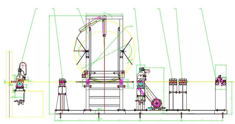
All steel structures are hardened by heat treatment
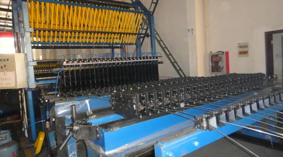
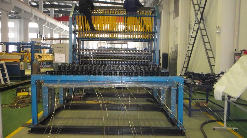
Equipment for straightening continuous wire.
Wire diameter: Ø 5 mm – Ø 12 mm.
The wire diameter can be changed without having to replace the straightening rollers.
Overall dimensions: 2.8 m × 3.2 m × 1.2 m (length × width × height),
Weight: 7,000 kg
2.3 Linear wire feeding system
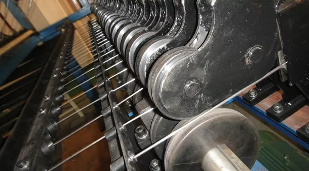
A total of 30 linear wire tensioning system sets
Each set can be controlled separately
All pneumatic components of the accumulator use branded systems, which facilitates their replacement and maintenance.
2.5 Cross-wire feeding device
The cross-wire cutting mechanism is installed above the mesh pulling system, which consists of the first cross-wire magazine, a platform for laying the cross-wire material, and a branching and removal mechanism. The branching and removal movement is performed by a pneumatic cylinder, operating in accordance with a set programme. The cross-wire cutting mechanism is the main component of the welding machine, and the speed at which the cross-wires are branched off, as well as the smoothness of this process, are key factors affecting the welding speed of the machine.
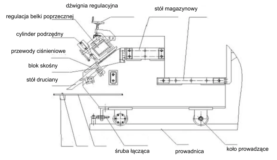
Feeding and storage system for cross-bars
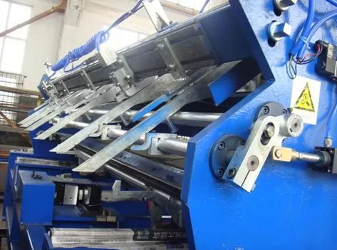
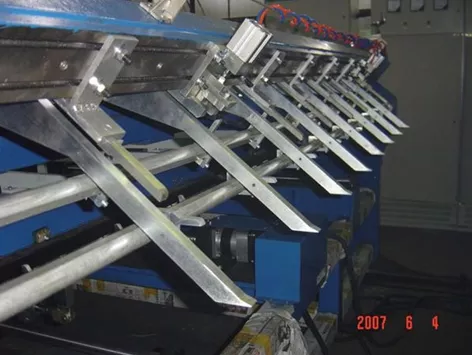
The cross-bars stored on the storage platform are arranged in an inclined slide chute, along which groups of separating needles are positioned. Two groups of distribution needles are controlled by a distribution actuator and move up and down along the normal direction of the slide chute. In accordance with the set procedure, the actuators work together to ensure accurate separation of the cross-bars.
The position of the pressure line and the branching needles must be adjusted during the first welding operation. Adjustment of the clamping line involves loosening the clamping line and adjusting the beam fixing bolt. The distance between the clamping line and the punching stand must be adjusted so that it is 1–2 mm greater than the diameter of the cross-beam to be welded, and bear in mind that the distance between the pressure line and the punching stand should be the same at the top and bottom; it is not permissible for this distance to be greater at the top and smaller at the bottom, or smaller at the top and greater at the bottom; the bolt should then be tightened.
2.6 Welding system
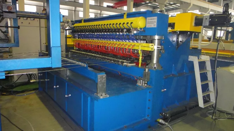
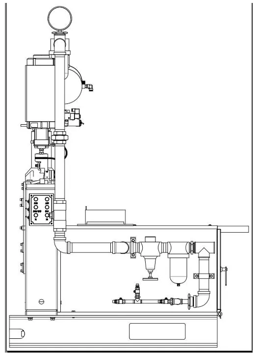
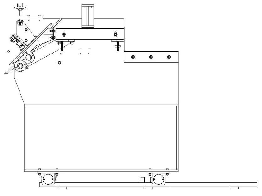
Side view
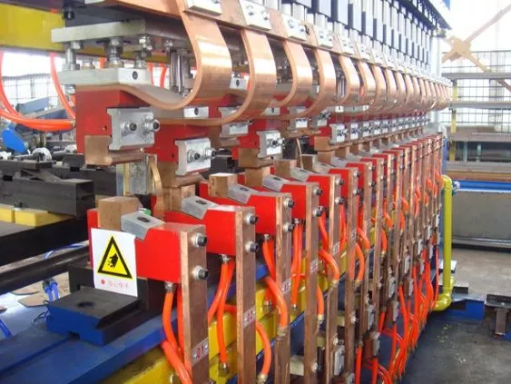
Rear view
| Diameter | 100×100 | 100×150 | 100×200 | 200×200 | 200×150 | 200×100 |
|---|---|---|---|---|---|---|
| Φ 5 | 2263.8 kg/h | 2841.3 kg/h | 3418.8 kg/h | 2310 kg/h | 2009.7 kg/h | 1709.4 kg/h |
| Φ 6 | 2937.06 kg/h | 3686.34 kg/h | 4435.56 kg/h | 2997 kg/h | 2607.42 kg/h | 2217.78 kg/h |
| Φ 8 | 4633.44 kg/h | 5815.44 kg/h | 6,997.44 kg/h | 4,728 kg/h | 4,113.36 kg/h | 3,498.72 kg/h |
| Φ 10 | 6338.64 kg/h | 7955.64 kg/h | 9572.64 kg/h | 6468 kg/h | 5627.1 kg/h | 4786.32 kg/h |
| Φ 12 | 7832.16 kg/h | 9830.16 kg/h | 11828.16 kg/h | 7,992 kg/h | 6,953.04 kg/h | 5,914.08 kg/h |
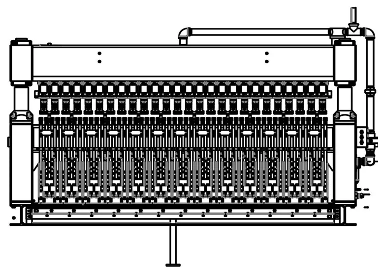
Wire spacing: 100×100 mm, adjustable as required.
Wire mesh welding machine with stepless adjustment of transverse and longitudinal wire spacing; longitudinal wire spacing is adjusted manually; transverse wire spacing is adjusted via an electrical control cabinet.
The welding system is designed for smooth and ribbed wire.
| Parameter | Value |
|---|---|
| Max. mesh width (transverse wire length) | 3000 mm |
| Wire spacing | 100 mm, freely programmable spacing |
| Cross-wire spacing | 100 × 100 mm, 150 × 150 mm, 200 × 200 mm |
| Line wire diameter and feed | Φ5–Φ12 mm, from a spool |
| Transverse wire diameter and feed | Φ5–Φ12 mm, PRECUT |
| Number of transformers | 15 × 125 kVA |
| Max. welding speed | 60–70 passes/min |
| Air consumption | ≥0.8 MPa, 2 m³/min |
| Cooling water consumption | ≥0.3 MPa, 3 m³/min |
| Overall machine dimensions | 4.1 × 1.2 × 2.5 m (L × W × H) |
| Air compressor requirements | Min. 0.7 MPa, 4 m³/min |
| Cooling water requirements | Min. 0.2 MPa, 2 m³/min |
| Total machine weight | 7000 kg |
| Parameter | Value |
|---|---|
| Number of welding transformers | 12 |
| Number of pneumatic cylinders (welding press) | 12 |
| Number of electrodes | 24 |
| Electrical power of the welding transformer | 15 × 125 kVA, 380 V / 50 Hz / 3-phase |
| Compressed air consumption | ≥4 m³/min |
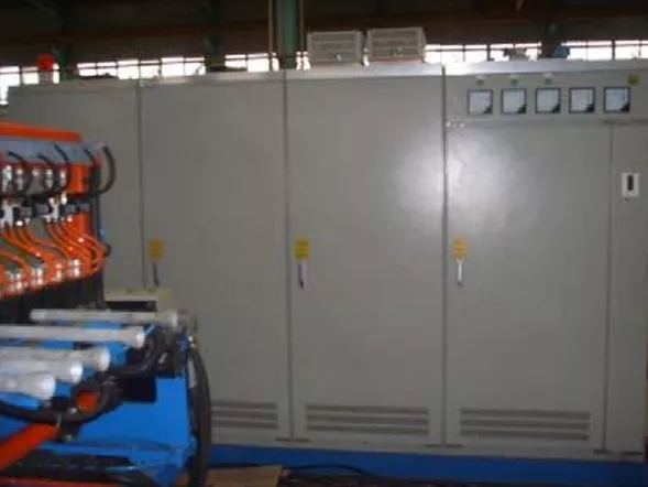
German Siemens 1 control unit
PLC servo control unit and
Siemens display
Other electrical components from OMRON
Control language: English, with touchscreen
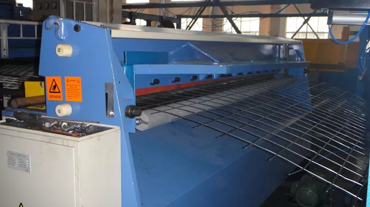
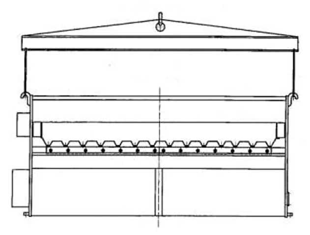
2.9 Wire mesh cutting machine
| Parameter | Value |
|---|---|
| Cutting speed | 50 times/min |
| Cutting capacity | 12 mm + 12 mm |
| Mesh cutting | automatic |
| Mesh cutting width | 2500 mm |
| Mesh cutting type | mechanical |
| Overall dimensions | 3.2 × 1 × 1.6 m (L × W × H) |
| Weight | 5000 kg |
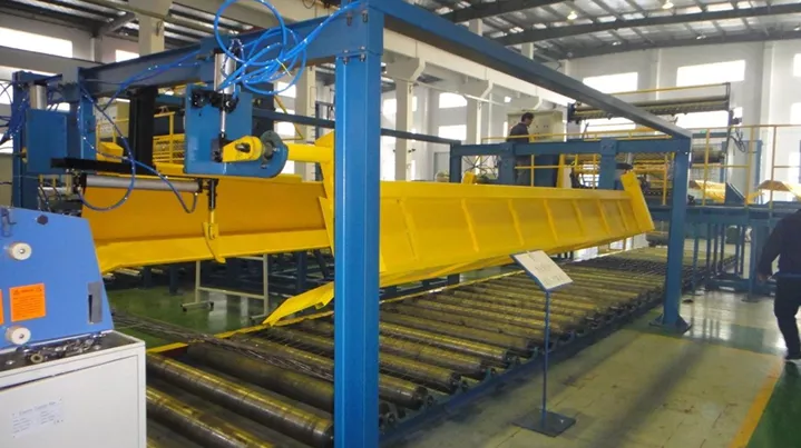
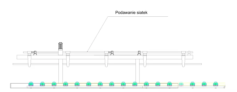
2.10 Sheet collection table
| Parameter | Value |
|---|---|
| Maximum sheet length | 14,000 mm |
| Maximum sheet weight | 1,000 kg |
| Feed type | pneumatic |
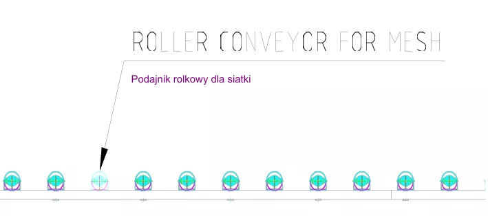
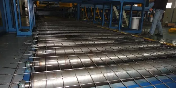
2.11 Sliding table with mesh
| Parameter | Value |
|---|---|
| Movable mesh table – length | 28 m × 2.4 m |
| Roller diameter | 120 mm |
| Motor | 5.5 kW |
| Weight | 5 tonnes |
| Overall dimensions | 24 × 3.2 × 2.2 m (L × W × H) |
| No. | Name | Quantity |
|---|---|---|
| 1 | Wire drop piston | 1 |
| 2 | Diffusion piston | 1 |
| 3 | Solenoid valve 1 | 1 |
| 4 | Solenoid valve 2 | 1 |
| 5 | Switch | 1 |
| 6 | Fast-acting fuse | 2 |
| 7 | Water valve | 1 |
| 8 | Microswitch | 1 |
| 9 | Touch switch | 1 |
| 10 | Key switch | 5 |
| 11 | Round magnet | 5 |
| 12 | Phosphorus clip | 5 |
| 13 | Electrode | 6 |
| 14 | Top electrode / copper tape | 2 |
| 15 | Copper transformer strip | 2 |
| 16 | Square metre | 1 |
| 17 | Square metre 2 | 1 |
| 18 | Quick connector | 1 |
| 19 | Quick connector 2 | 1 |
| 20 | Quick-connect 3 | 1 |
| 21 | Quick-connect 1/4” | 1 |
| 22 | 1/8” | 1 |
| 23 | Oil | 1 |
| 24 | Electronic card | 1 |
2.12 High-performance wire straightening and cutting machine
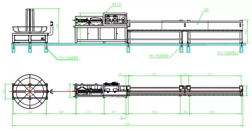
This high-speed straightening and cutting machine is suitable for cutting and straightening wire in coils, hot-rolled bars and cold-rolled ribbed steel; it does not cause scratches to the ribs and is characterised by tight cutting tolerances, good straightness, ease of operation and high productivity. The machine mainly consists of an uncoiler, a straightening unit (double traction, chain drive), a flying-wheel cutter, an electrical cabinet and a 12-metre collection rack.
Ribbed wire diameter: 5–12 mm Material: HRB335 hot-rolled steel bars; deformed and smooth wire Speed: max. 160 m/min Cutting length: 1–12 m Straightening tolerance: ≤2 mm/m Cutting length tolerance: ≤2 mm with approximate switch Total power: 22 kW
v
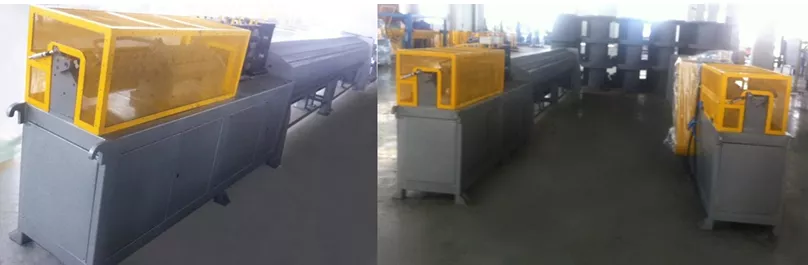
The high-speed straightening and cutting machine is suitable for cutting and straightening wire in coils, hot-rolled bars and cold-rolled ribbed steel; it does not cause scratches to the ribs and is characterised by tight cutting tolerances, good straightness, ease of operation and high efficiency. The machine consists mainly of a decoiler, a straightening machine (double traction, chain drive), a flying-wheel cutter, an electrical cabinet and a 12-metre collection rack.
| Parameter | Value |
|---|---|
| Ribbed wire diameter | 5–12 mm |
| Material | HRB335 hot-rolled steel bars; deformed and smooth wire |
| Speed | max. 160 m/min |
| Cutting length | 1–12 m |
| Straightening tolerance | ≤2 mm/m |
| Cutting length tolerance | ≤2 mm |
| Total power | 22 kW |
| Total weight | 3500 kg |
| Machine dimensions | 17 × 2 × 2 m (L × W × H) |
Cooling tower
| Parameter | Value |
|---|---|
| Equipment | Air compressor |
| Model | LG-6/7 |
| Outlet pressure | 0.7 MPa |
| Shaft power | 6.0 kW |
| Capacity | 36.0 m³/min |
| Electric motor power | 37 kW |
| Rotational speed | 1050 rpm |
| Weight | 4,300 kg |
| External dimensions | 1,300 × 1,100 × 1,660 mm |