








Digima die for AMADA press brake, 800x120x26, 2 segments, L = 1600 mm, 63T



Digima die for an AMADA press brake, TYPE 800x120x26, 2 segments, L=1600mm, 63T pressure
We are pleased to present a professional Digima upper die, designed for use on high-pressure press brakes (up to 63 tonnes) fitted with the Amada clamping system. This tool has been designed for processes requiring high precision and durability under intensive industrial use. The punch is made from high-grade T8A tool steel, which ensures excellent resistance to deformation and fracture under load.
The key manufacturing process used in this model is high-frequency induction hardening of the cutting edge, which has achieved a hardness of HRC 45 ± 2 degrees. This hardness ensures that the punch tip retains its geometry for a very long time, which translates into consistent bending angles and eliminates the need for frequent tool servicing. The set consists of two segments, each 800 mm long, giving a total working length of 1,600 mm. Precise grinding of the contact surfaces ensures that the misalignment at the segment joints does not exceed 0.05 mm, enabling a uniform bending line across the entire width of the sheet metal being processed.
Suitable for the PBH-63x1600 press and others of these dimensions

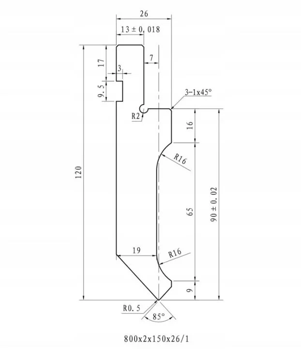
Full technical specifications and design parameters
Below is a complete list of the technical specifications for the punch and die, compiled on the basis of the design drawing:
Geometric and working dimensions:
- Total height of the tool: 120 millimetres.
- Functional height (from the base plane to the bending axis): 90 plus or minus 0.02 millimetres.
- Total width of the punch: 26 millimetres.
- Body width in the working section: 19 millimetres.
- Punch cutting edge angle: 85 degrees.
- Radius of the working nose: R 0.5 millimetres.
Mounting and profile parameters:
- Standard upper mounting dimension: 13 plus or minus 0.018 millimetres.
- Dimensions of the retaining slot: height 9.5 millimetres with a cut-out depth of 3 millimetres.
- Socket positioning: distance of 17 millimetres from the upper edge of the punch and an axial offset of 7 millimetres.
- Design radii: an arc at the socket with a radius of R 2 and body profile arcs with a radius of R 16.
- Edge chamfering: type 1 chamfer at 45 degrees, applied at three points on the profile.
- Profile section heights: upper straight section 16 millimetres high, side section 65 millimetres long and lower foot 9 millimetres high.

Manufacturing standards and tolerances:
- Heat treatment: high-frequency hardening of the cutting edge to a hardness of HRC 45 ± 2 degrees.
- Fitting accuracy: the error at the segment joints when operating as a set does not exceed 0.05 millimetres.
- Geometric tolerances: the tool’s parallelism and perpendicularity errors are maintained within limits of less than or equal to 0.05 millimetres.
- End-face finish: all edges at section joints, except for the cutting edge, are rounded to a radius of R 0.5 millimetres.
- Set configuration: total length comprising 2 segments, each 800 millimetres long.
*The photographs are for illustrative purposes only; the main image shows the cross-sectional shape of the tool as depicted in the technical drawing (without indicating the length), whilst the side view provides an example of what such a segment would look like in reality